3D CAD for product design
At Bang Creations we use the latest software from SolidWorks for our 3D CAD design. It is integral for all stages of the development cycle, apart from concept design where we prefer to stick with pen and paper.
3D CAD software is used to design, develop, and engineer product components and assemblies within a virtual 3D space. Whereas traditionally 2D software such as AutoCAD was used to design components. The issue with 2D design is that you cannot easily understand how components interact together, nor how a component would look in 3D space.
We utilise SolidWorks to accelerate the development process, allowing us to create precise 3D prints, engineering drawings, or for FEA and computational simulations.
The challenge
We were tasked with the design and manufacture of a stand to fit all VR headsets, that will protect and store the expensive equipment. The stand needed to include USB ports and charge controllers to allow the user to charge their equipment whilst it is being stored.
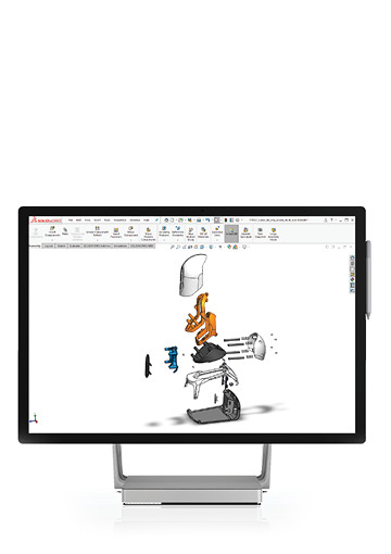
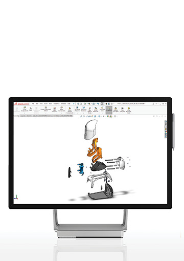
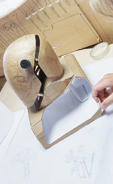
After concept design on paper, along with some hand prototyping we were ready to work up the design in CAD. The modelling of this product; named Voya, would be complex. The design has compound curves, engineered mechanisms, and also had to house electronics.
The majority of components were to be injection moulded, so required consideration on the mould direction, wall thickness, and draft angles.
The solution
The best method to create 3D designs using SolidWorks is by top-down modelling the components parametrically (meaning that the model can dynamically change when one component is altered). This requires the use of detailed relations and equations which size the components relative to one another. Once the model is completed it allows for more efficient engineering iterations, accelerating the product design development process.
Design for manufacture
Design for manufacture (DfM) was a prevalent in the 3D design process. Every plastic component had to be designed with a constant wall thickness, with ribs and design features being of a smaller thickness to avoid defects in the final product such as sink marks. A minimum draft angle of 1° had to be maintained on all polished surfaces of the product, with a larger draft for non-polished internal surfaces. Parametric modelling equations were key for maintaining these detailed features.
Tolerancing and accumulative tolerances also had to be considered. 3D CAD allows for quicker evaluation of these tolerances, as you can visually see clearances needed, and build in tolerances from this into engineering drawings.
The outcome
Once Voya had been fully designed in 3D CAD, the design, particularly it's DfMA (Design for Manufacture & Assembly), was ratified using our virtual reality system. We were able to observe and interact with the CAD model in a virtual 3D space, giving us the ability to look inside the design, check mechanisms, draft angles, wall thicknesses and more.
After the design had been approved we created 3D engineering drawing packs for manufacture, which included tolerances and assembly details. This was sent to our manufacturing partner to obtain a product costing.
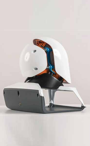
The prototype
The CAD was also used for a 3D printed and CNC'd works like looks like prototype (WLLL). This was used by the client for initial product demonstrations to procure interest in the potential of the product.

3D CAD for product design
At Bang Creations we use the latest software from SolidWorks for our 3D CAD design. It is integral for all stages of the development cycle, apart from concept design where we prefer to stick with pen and paper.
3D CAD software is used to design, develop, and engineer product components and assemblies within a virtual 3D space. Whereas traditionally 2D software such as AutoCAD was used to design components. The issue with 2D design is that you cannot easily understand how components interact together, nor how a component would look in 3D space.
We utilise SolidWorks to accelerate the development process, allowing us to create precise 3D prints, engineering drawings, or for FEA and computational simulations.
The challenge
We were tasked with the design and manufacture of a stand to fit all VR headsets, that will protect and store the expensive equipment. The stand needed to include USB ports and charge controllers to allow the user to charge their equipment whilst it is being stored.
After concept design on paper, along with some hand prototyping we were ready to work up the design in CAD. The modelling of this product; named Voya, would be complex. The design has compound curves, engineered mechanisms, and also had to house electronics.
The majority of components were to be injection moulded, so required consideration on the mould direction, wall thickness, and draft angles.
The solution
The best method to create 3D designs using SolidWorks is by top-down modelling the components parametrically (meaning that the model can dynamically change when one component is altered). This requires the use of detailed relations and equations which size the components relative to one another. Once the model is completed it allows for more efficient engineering iterations, accelerating the product design development process.
Design for manufacture
Design for manufacture (DfM) was a prevalent in the 3D design process. Every plastic component had to be designed with a constant wall thickness, with ribs and design features being of a smaller thickness to avoid defects in the final product such as sink marks. A minimum draft angle of 1° had to be maintained on all polished surfaces of the product, with a larger draft for non-polished internal surfaces. Parametric modelling equations were key for maintaining these detailed features.
Tolerancing and accumulative tolerances also had to be considered. 3D CAD allows for quicker evaluation of these tolerances, as you can visually see clearances needed, and build in tolerances from this into engineering drawings.
The outcome
Once Voya had been fully designed in 3D CAD, the design, particularly it's DfMA (Design for Manufacture & Assembly), was ratified using our virtual reality system. We were able to observe and interact with the CAD model in a virtual 3D space, giving us the ability to look inside the design, check mechanisms, draft angles, wall thicknesses and more.
After the design had been approved we created 3D engineering drawing packs for manufacture, which included tolerances and assembly details. This was sent to our manufacturing partner to obtain a product costing.
The prototype
The CAD was also used for a 3D printed and CNC'd works like looks like prototype (WLLL). This was used by the client for initial product demonstrations to procure interest in the potential of the product.